
Why Light Bulbs Glow Brighter When Connected In Parallel
Suppose you are studying the patterns of electrical circuits or have come across a situation where you are looking at wiring lighting in parallel vs in series. In that case, you may wonder why light bulbs end up glowing brighter when connected in series.
The reason light bulbs glow brighter in a parallel circuit is that the voltage remains the same for all bulbs when connected in parallel. When lights are connected in series the voltage is split between all the lights in the series, which causes them to be dimmer than their parallel equivalent.
This all comes down to parallel circuits allowing for a higher power output per electrical load put on the circuit. This is due to how the electrical circuit behaves when multiple loads are connected in this matter.
Going from here we will explain what happens when lights are connected in parallel and series and explain what happens to the current in the circuit in each instance.
What Are Parallel And Series Circuits?
To properly answer this question we first need to dive deeper into the definitions and distinctions between parallel and series electrical circuits.
As you can tell by their names, it refers to the way the electrical loads are connected in the circuit in relation to each other.
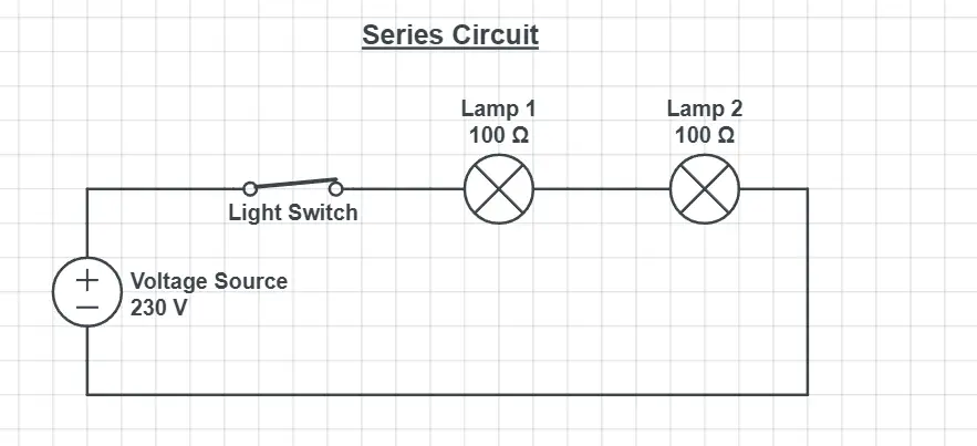
If the lights are connected one after another like a Christmas light string it is a series circuit but if the power is supplied directly to each load and connected back together at their neutral point it is considered a parallel circuit.

In these circuits, you can add on as many electrical loads as you wish as long as the power supply can support the loads connected to it.
While this is the most basic way to define the difference between these circuits it may not always be super clear what the circuit is.
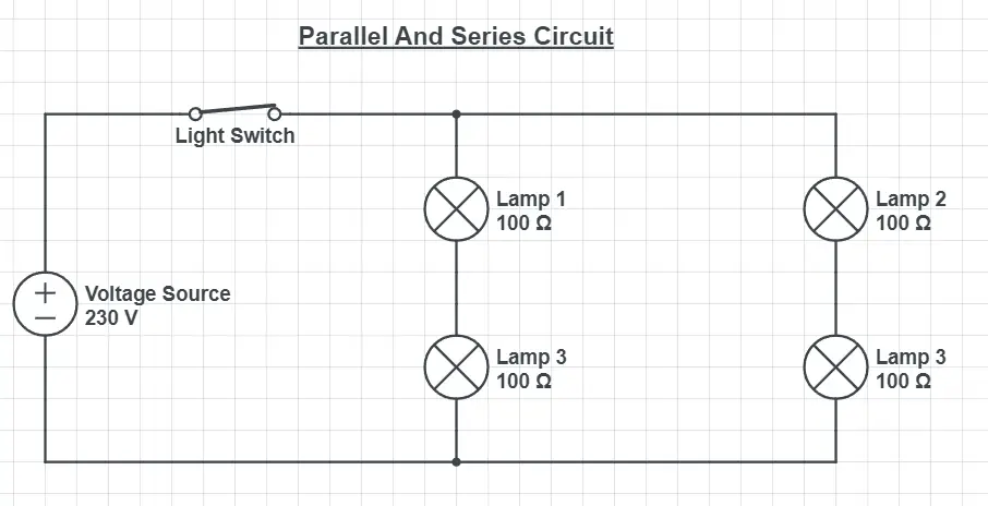
For example, you could have a parallel circuit where in each parallel section there are several lights connected in series. This would technically be both a parallel and series circuit since both take place, but generally, a circuit like this will be treated like a parallel circuit.
While a circuit like this is uncommon in most installations it is valuable to know that circuits aren’t always strictly parallel or series circuits. In most instances, circuits are one or the other.
To deal with a circuit like this you would try to simplify the loads by adding together the lights in series and then treating it like a parallel circuit.
The Relationship Between Voltage, Resistance And Current
Now that we have established the differences between how these circuits are constructed we can look at how the electrical current actually behaves when subjected to these circuits.
To do that we need a firm grasp of the components that make an electrical circuit function. These are:
- Voltage (V or U)
- Resistance (R or Ω)
- Current (A or I)
In simple terms, the voltage is the “force” in which the electrons are sent, resistance refers to the amount of electrical resistance the electrons face and the current is the total flow of electrons. These three components are present in every single electrical circuit.
Voltage is measured in Volts (V), resistance is measured in Ohms (Ω) and current is measured in Amperes (A). The notations U, R and I and used more for theoretical calculations.
These three have a mathematical relationship to each other due to how they are related in the circuit. This relationship looks like this:
- Voltage (V) = Resistance (R) * Current (I)
This relationship is also known as Ohms Law and is the most fundamental formula for understanding electrical circuits. Since it is a mathematical formula it can also be bent to directly solve for resistance and current. Those variants would look like this:
- Current (I) = Voltage (V) / Resistance (R)
- Resistance (R) = Voltage (V) / Current (I)
All of these variants are useful to know since normally only 2 of these numbers are known or available to us, meaning we have to solve for at least one of them normally.
In a simple circuit, this relationship could look like this:

Since the voltage source supplies the circuit with a voltage of 230V and the lamp has a resistance of 100Ω it means the current will have a size of 2.3A.
For most Europeans, the voltage level in your outlets will be in the range of 220-240V whereas it is most commonly 120V in the United States.
How The Electrical Circuit Behaves When Wired Parallel
Now that we have a better understanding of the component’s voltage, current and resistance we can dive deeper into what happens to these when the circuit happens to be wired in parallel.
When a circuit is wired in parallel the voltage level stays the same for all the loads. This is simply due to the fact that all the loads have a direct connection to the positive and negative poles of the voltage source. Any load that is directly connected to the two points like this will receive the source’s maximum voltage output.
When it comes to the current of the circuit it is also rather simple. It simply splits between the different loads in order to power them. The amount of Amps depends entirely on the resistance of the individual loads since it spreads based on that.
As for the resistance, things change quite a bit though. When two or more loads are connected in parallel with each other it actually makes the total resistance of the circuit decrease even though you are adding more loads.
This may sound strange but it is for a simple reason. An electrical current always takes the path of least resistance to its destination.
When you add another load to a circuit parallel to the original load it creates another path to that very same destination. You can imagine this being the same thing as adding another lane to a highway. You simply get another road that allows for more traffic to the same destination.
The formulas for total resistance in a parallel circuit end up looking like the following.
- The formula for only 2 loads in parallel: (R1 * R2) / (R1 +R2)
- The formula 2 or more loads in parallel: 1/Rtotal = 1/R1 + 1/R2 + 1/R3…
The first formula is pretty straight forwards but the second is a bit more complex. The simplest way to describe it is that you take the resistance value for all the loads and divide 1 by that value. If you then add all that together and divide 1 by that value you’ll end up with the total resistance for the circuit.
Parallel Circuit Example Calculation
For you to fully grasp the concept of this and why this makes light bulbs glow brighter than those connected in series we have an example circuit below where we have run the calculations for you.
In this example, we have three different lights connected in parallel.
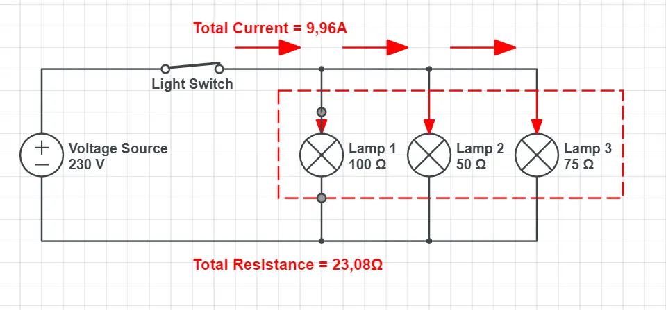
To begin we need to calculate the total resistance (Rtotal) of the entire circuit using the formula mentioned above. In this scenario, this would look like the following.
- 1/100 + 1/50 + 1/75 = 0,04333…
- 1/0,04333 = 23,08Ω
In this instance, the total resistance ends up being 23,08Ω. A good rule of thumb to know if you got the number right is to see if it’s below the lowest resistance in the circuit since this number should always be lower than that.
The reason for that is that you give the electricity another path, which alleviates some of the currents from the lowest resistance, meaning the overall electrical resistance decreases.
With this said, we also know that the voltage supplying this circuit is 230V. Using these numbers and ohms law we can calculate the current of the circuit.
- 230V / 23,08Ω = 9.96A
For this circuit, we now know the total current, resistance and voltage.
However, much unlike series circuits, the power output of these bulbs ends up being much higher than if they were connected in series.
Power or Watts (W) is equal to the voltage (V) times the electrical current (A). Since each bulb benefits from the full voltage and receives its own current in relation to how big the load is the number of watts each bulb produces ends up being much larger than if they were connected in series.
As described above, the mathematical formula for this ends up looking like this:
- Power (W) = Voltage (V) * Current (A)
This is exactly why light bulbs glow brighter in parallel than in series. It is because when they are connected in parallel the voltage and current are higher than in a series circuit, which causes the number of Watts to increase significantly.
Watts refers to the electrical power of an appliance or in this case light. The higher the watt is for the light the brighter it will glow, as long as the bulb is able to handle it.
With all this said, since the bulbs in our example have different resistances they will individually produce different current sizes and therefore different power levels, meaning that they would not glow with equal intensity.
Why Lights Glow Dimmer When Connected In Series
Now that we have discussed what happens to the electrical circuit when it’s connected in parallel we can look at what happens when it’s connected in series.
Series circuits are pretty simple by nature. As for the resistances, you simply add the values together and that becomes the total resistance.
After you know the resistance you need to know either the voltage or current to know the value for the other in the circuit, but this is all easily calculated with Ohms’s law.
The main difference in how these circuits behave though has to do with the voltage. As previously explained, in a series circuit, the voltage ends up being split up between the loads on the circuit.
This is because the total resistance ends up being higher in series which creates a smaller current. When the smaller current is then multiplied by each individual bulb’s resistance you end up with a voltage over the bulb which is less than the total voltage of the circuit.
Since the current and the voltage end up being less over each individual bulb in a series circuit this also means that the total Power (W) ends up being less, which causes them to glow dimmer than parallel lights.
Series Circuit Example Calculation
To illustrate why lights glow dimmer we have an example calculation for a series circuit.
For comparison’s sake, we will use the exact same lights for the parallel circuit so you can see how it differentiates.
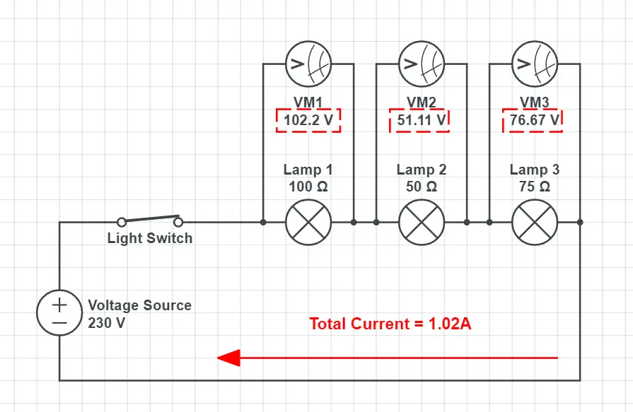
This circuit uses the exact same lights as the loads but as you can see the current ends up being much lower at 1.02A.
This is because when the lights are connected like this we simply add the resistances up together like this.
- 100Ω + 50Ω + 75Ω = 225Ω
- 230V / 225Ω = 1.02A
Based on this information we now know that the current for the entire circuit is 1.02A. By multiplying this number with each individual resistance of the lights the result is the voltage that the light is supplied with.
This is indicated in the image by the marked voltages above the lights. The “VM” stands for Voltage Meters and in the example, they are measuring the voltage over each light.
Since the formula for power (W) is a light’s voltage times the current you can see clearly why lights produce far less power when connected in series.
Since the total resistance in a series circuit ends up higher than in a parallel circuit the current in turn becomes less than its parallel counterpart. In the context of the formula for power (Watts (W) = Voltage * Current) we are significantly reducing both components by connecting the loads in series since the voltage also ends up being split.
Summary
To summarize all of this, the main takeaway is that lights connected in parallel will end up producing more power than the same lights would when connected in series.
This is because when a circuit is parallel it allows for a greater current to the lights since all the lights also get supplied with the maximum available voltage.
This is contrary to a series circuit since in a series circuit the voltage is split between the different lights since the resistances are placed one after another. This causes the total power to be less since the current in the circuit and the voltage over each individual bulb is lower than its parallel equivalent.

10 Facts About Compact Fluorescent Light Bulbs
Why Tungsten Is Used In Light Bulb Filaments

Why Light Bulbs Break When Switched On
About The Author
Daniel Janzon
Hello, I'm Daniel, the author behind this article and owner of this website! I'm a young soul at 23 years old with a passion for everything lighting since I find it very fascinating in general. I studied light planning for 2 years in Stockholm, Sweden and now work with light planning full time.